Post by: ebphondaprelude on January 01, 2007, 07:09:00 PM
what sux is the controllers only output 2.8v, so i need to find sum 2.8v leds or juice up the power with a transistor or something.
they still look good but could be a little brighter.
i also noticed their was a pad labeled led5 under the ps button, i soldered an led in play but i could not get it to light up, so i grounded one end and the other end i put to the red wire right above it
Stock board
(IMG:http://myacc.net/~euphoriclab/pix/ps3/cont1.JPG)
Board with 5th led
(IMG:http://myacc.net/~euphoriclab/pix/ps3/cont3.JPG)
Final Product
(IMG:http://myacc.net/~euphoriclab/pix/ps3/cont5.JPG)
This post has been edited by ebphondaprelude: Jan 2 2007, 03:10 AM
Post by: pablot on January 01, 2007, 10:42:00 PM

/pablot
Post by: ebphondaprelude on January 02, 2007, 06:14:00 AM
ill check into it sum more 2day, i was a bit tired last night and i figured it would work heheh
Post by: pablot on January 02, 2007, 06:57:00 AM
/pablot
Post by: spinr34 on January 02, 2007, 10:55:00 AM

Post by: ebphondaprelude on January 02, 2007, 06:53:00 PM
http://www.engadget....e-led-makeover/

Post by: grim_d on January 02, 2007, 07:17:00 PM
funny they put this on engadget, maxconsole (i posted in their forums) ps3.qj
http://www.engadget....e-led-makeover/
congrats mate, being featured is cool.
Post by: PDAIsAok on January 02, 2007, 10:14:00 PM
(IMG:http://img.photobucket.com/albums/v480/PDAisAok/DSC01179.jpg)
(IMG:http://img.photobucket.com/albums/v480/PDAisAok/DSC01178.jpg)
(IMG:http://img.photobucket.com/albums/v480/PDAisAok/DSC01177.jpg)
Post by: grim_d on January 03, 2007, 06:23:00 AM
Post by: pablot on January 03, 2007, 08:15:00 AM
Post by: ebphondaprelude on January 03, 2007, 08:46:00 AM
maybe a 3m will work better.
BUT YES SONY SHOLD HAVE INCLUDED THE MYSTIROUS 5TH LED
BTW how did you solder that LED? did you use the same points as i did? 2.8v? i couldnt find a 3.3v switchable source, the ones i tried the led always stayed on and didnt turn off witht he controller.
This post has been edited by ebphondaprelude: Jan 3 2007, 04:49 PM
Post by: PDAIsAok on January 03, 2007, 08:49:00 AM
I used the same solder points as you did eb, the only thing I had to change was cut into a few parts on the controller for it to actually fit in there, it's pretty snug
Something I noticed when I went to walmart to buy a spare controller (aside from the PS3s that they couldnt get rid of) was a stock photo of a PS3 controller with a red lit PS button. Looks as though they originally planned on having that light up red just never got around to it for some reason
(IMG:http://img.photobucket.com/albums/v480/PDAisAok/DSC01182.jpg)
This post has been edited by PDAIsAok: Jan 3 2007, 05:05 PM
Post by: PDAIsAok on January 03, 2007, 09:22:00 AM
(IMG:http://img.photobucket.com/albums/v480/PDAisAok/DSC01191.jpg)
Post by: ebphondaprelude on January 03, 2007, 09:56:00 AM
(sorry current gen you get cut out this pic)
(IMG:http://myacc.net/~euphoriclab/pix/other/all1.jpg)
(IMG:http://myacc.net/~euphoriclab/pix/other/all2.jpg)
This post has been edited by ebphondaprelude: Jan 3 2007, 05:56 PM
Post by: PDAIsAok on January 03, 2007, 10:05:00 AM
Post by: ebphondaprelude on January 03, 2007, 10:12:00 AM
i just noticed Nice faceplate on the 360, i really wish they came out with a case that the pattern continues to the sides.
How do you like the HD-DVD player. im not a big movie fan so i havnt got one yet. plus now i got blue-ray so i dont kno if its worth it. maybe a bit down the road when i can get em a lil cheaper
Post by: PDAIsAok on January 03, 2007, 10:40:00 AM
Post by: mrcmax on January 03, 2007, 01:42:00 PM
Post by: PDAIsAok on January 03, 2007, 04:11:00 PM
(IMG:http://img.photobucket.com/albums/v480/PDAisAok/DSC01195.jpg)
(IMG:http://img.photobucket.com/albums/v480/PDAisAok/DSC01196.jpg)
(IMG:http://img.photobucket.com/albums/v480/PDAisAok/DSC01197.jpg)
Post by: hyoo82 on January 03, 2007, 04:17:00 PM
Post by: ebphondaprelude on January 03, 2007, 04:25:00 PM
nice lookin, the 3mm looks better i might try one their later
Now you gotta do the top SMD leds to match ;-)
Post by: grim_d on January 03, 2007, 05:08:00 PM
Post by: PDAIsAok on January 03, 2007, 06:25:00 PM
QUOTE(hyoo82 @ Jan 3 2007, 05:24 PM) 
instructions!! instructions!!! soldering stuff is fun! but poking my finger with a hot iron isn't fun if there isn't a set of instructions to follow!!!!! with a desired result (this case, Blue LED controller)
parts needed:
PS3 controller
3mm LED (or 5mm if you want a really bright light, its a tight squeeze)
some wire
some solder
some patience
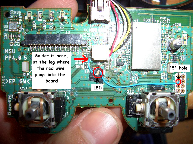
First you need to solder some short wires to the PCB board @ the "5" hole on the right side, and at the leg where the red wire plugs into the middle of the board. you will then solder an led to these 2 wires, do this while the controller is on so you can make sure it works. If you are using a 3mm or 5mm rather than the size eb used, you must melt or cut the black piece of plastic that is a cylinder under the PS button. It is the cylinder that the clear rubber piece slides into. This will allow the LED to sit in this cylinder directly under the PS button. you will also have to cut the part of the clear rubber piece that goes down into this cylinder. Leave enough to where it still sits in the rubber holster. After this is all done you should be able to just close it up and be done. BEFORE you put it all back together put the analog sticks back on the board and make sure they dont hit the wires to the LED (this happened to me and I had to make some adjustments.
QUOTE(ebphondaprelude @ Jan 3 2007, 05:32 PM)
thx thx
nice lookin, the 3mm looks better i might try one their later
Now you gotta do the top SMD leds to match ;-)
Do you know of a good source for those smaller LEDs? I couldnt find any in town where I am so I figure I'll have to order them online
This post has been edited by PDAIsAok: Jan 4 2007, 02:30 AM
Post by: entermymatrix03 on January 03, 2007, 08:10:00 PM
also, would THIS 1.8mm LED work? would i need to alter my controller in any way to make this fit?
awsome mod, thanks man!
Post by: PDAIsAok on January 03, 2007, 09:03:00 PM
QUOTE(entermymatrix03 @ Jan 3 2007, 09:17 PM) 
Can you take some pics of the underside of the PCB? I'm not quite understanding what you are soldering to. So you just solder one wire, for the positive pole, to the red on that connector and then for the ground you solder to the "5" hole?
also, would THIS 1.8mm LED work? would i need to alter my controller in any way to make this fit?
awsome mod, thanks man!
That LED looks to be 2.5v max and I believe you'll be getting 2.8 from this remote, so it may be too much for that LED, im not for sure on that though. Id recommend going with a 3mm or using what eb originally posted with. That is a great price though, I paid nearly $5 for a 5mm blue LED at Radio Shack. Also you dont need to solder anything to the bottom of the pcb. There are a few pads for ground but you can just solder it to that hole that is labeled 5. Some of those other holes, or all of them, may be grounds I didnt test any of the other ones. Just went with what eb did.
Hey eb, what size SMDs are those? I see PLCC2, 1206, 0805, and 0603 available. Are they very difficult to solder? Ive never messed with LEDs like that
Post by: Laeq on January 03, 2007, 10:03:00 PM
but I finally finished doing this, though I didn't change the color
I couldn't find any surface mount LEDs (they aren't sold in my area).
I used a 3mm red LED, and it worked perfectly, albeit it's a bit dim, but it's fine. Pluse, with a little modification to that translucent column under the PS button (i.e. cutting a small portion off), you can fit it right into the cylinder.
here's a pic (crappy, I know
 ):
):
Post by: ebphondaprelude on January 04, 2007, 08:59:00 AM
they are abuot the size of the letter E on the front of a dime
the wire that goes to the back goes to a PAD labeled GRD (ground) their are abuot 5 diffrent ones on the back to choose from.
Thx
<MikE>
QUOTE(PDAIsAok @ Jan 3 2007, 11:10 PM)
That LED looks to be 2.5v max and I believe you'll be getting 2.8 from this remote, so it may be too much for that LED, im not for sure on that though. Id recommend going with a 3mm or using what eb originally posted with. That is a great price though, I paid nearly $5 for a 5mm blue LED at Radio Shack. Also you dont need to solder anything to the bottom of the pcb. There are a few pads for ground but you can just solder it to that hole that is labeled 5. Some of those other holes, or all of them, may be grounds I didnt test any of the other ones. Just went with what eb did.
Hey eb, what size SMDs are those? I see PLCC2, 1206, 0805, and 0603 available. Are they very difficult to solder? Ive never messed with LEDs like that
Post by: numba107 on January 04, 2007, 04:06:00 PM
(IMG:http://i95.photobucket.com/albums/l157/draffpic07/GetAttachment.jpg)
this did take a while, i hate usin that iron thing
Post by: Fuel90 on January 04, 2007, 04:11:00 PM
Post by: entermymatrix on January 04, 2007, 04:51:00 PM
20 Assorted LED's The only thing is they don't tell you what is what inside the pack.
I also bought a 1.7 volt becuase the guy told me it would work but it has a 2.4v max....so i guess that one is out also. I just may take these back and order some from that site i posted up there...unless you guys think these may work.
What size guage wire are you guys using also and what do you put under the led to keep the contacts from touching the PCB? Never really worked with LED's, soldered a good bit and modded a few xbox's, but never messed with LED's....
a step by step with pics would be nice also! (IMG:style_emoticons/default/smile.gif) Thanks guys!
***edit*** - I'm also having a tough time finding 2.8v LED's. everything is between 2-2.6V max. can i still use those? Also, how does this fare against battery drain?
This post has been edited by entermymatrix: Jan 5 2007, 12:55 AM
Post by: FmanFORPS3 on January 04, 2007, 05:50:00 PM
QUOTE(Fuel90 @ Jan 4 2007, 06:18 PM)
an someone make a tut with pictures step by step? Cause I haven't really done something like this before. Thanks.
Yeah, neither have I and I would really appreciate it if someone would post instructions with pictures...
PCB board? PCM? I have no idea what you guys are talking about, but I would love to learn

Post by: numba107 on January 04, 2007, 06:27:00 PM
Post by: NeoSHODAN on January 04, 2007, 09:47:00 PM
(IMG:http://i130.photobucket.com/albums/p246/neverusedagain/rout1.jpg)
(IMG:http://i130.photobucket.com/albums/p246/neverusedagain/rout2.jpg)
If I'm right, that missing resistor is all that's stopping the empty LED 'socket' from working. Without it, the red trace is electrically isolated from the rest of the board. With it, the LED is tied to an IC of some nature, something I believe likely to maintain full functionality. (If they don't redesign the pads away, why change the IC out?) I'm assuming that the blue trace, as it was connected to many things other than just the LED, is fully functional without modification.
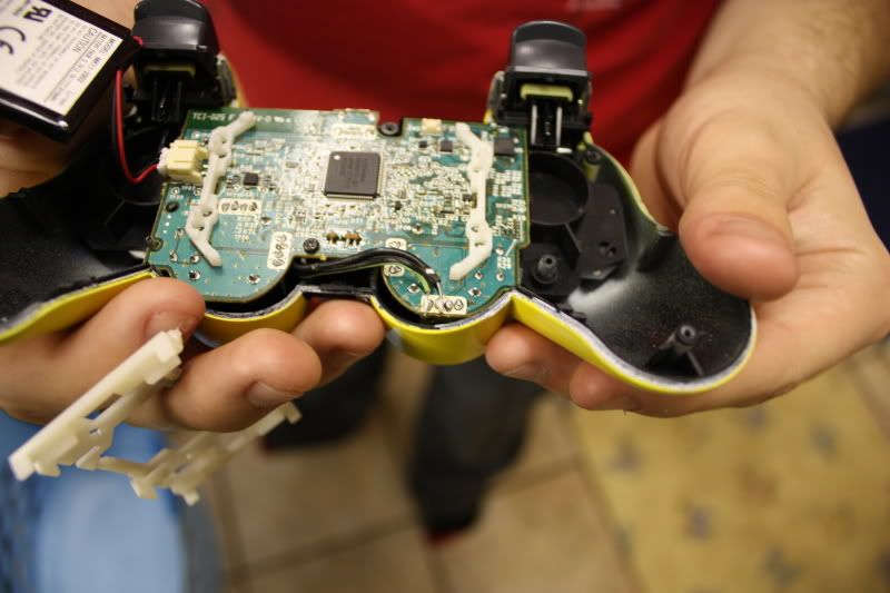
Now for a question of my own... removing the screws was easy enough. but there is a plastic catch that was difficult for me to open. I ended up using a screwdriver to push the pieces apart and the casing got some rather unpleasant-looking scratches. Is there an easy way to open the casing after the screws have been removed, or will I be scratching every controller I modify? I'm certainly hoping that sony designed it better than I think they did... I can see many controller casings being broken during battery replacement-attempts...
(the PCB photos I stole and highlighted were originally posted by ebphondaprelude and jeremydammit)
Post by: FmanFORPS3 on January 04, 2007, 10:15:00 PM

Also, how do I go about changing the four red LEDs (that tell you the controller port). So I just break them off and solder blue ones (that are also 2.8v)?
And my last question, does the center LED turn off when the controller is off? or does it continuously drain the battery? (I've heard from a different modder that his first attempt drained the battery even when its off...)
BTW great work guys...you make it seem so...easy!
Post by: ebphondaprelude on January 04, 2007, 11:26:00 PM
FmanFORPS3 - yes 2 wires the positive to the red wire and the ground to a ground, BTW their is no 2,8v blue leds, blue leds are 3.3v (at least to my knowledge)
and the led will turn off with the controller if you power it with the red wire as in the picture, if you go strait off the battery then it will always be on,
numba107 - AGREED, i didnt think their would be so much a need for a tutorial otherwise i would have made one, but then again i didnt expect a small led mod to get so much publicity
This post has been edited by ebphondaprelude: Jan 5 2007, 07:29 AM
Post by: pablot on January 05, 2007, 02:19:00 AM
Thats perfect. So all you need to do is add a resistor to that empty resistor footprint and a led to the led footprint. If the voltage is low enough you probably don't need a resistor there, you can just short the resistor out with some solder. Wonder it the led has any functionallity in the firmware or if it will be solid off? Someone try it! =)
/pablot
Post by: aaquib2 on January 05, 2007, 07:55:00 AM
Can someone post step by step pictures and instructions? It'd be greatly appreciated.
Post by: entermymatrix on January 05, 2007, 09:13:00 AM
one quick question, you guys using the 5mm leds...did you put the led in the black hole under the PS button? how snug was the fit and how much of the clear plastic did you have to remove? Thanks!
Post by: FmanFORPS3 on January 05, 2007, 01:38:00 PM
(yeah, I used paint
 )
)BTW, I know I'm repeating all of this, but I'm sure some people will still be confused..
Post by: ebphondaprelude on January 05, 2007, 02:44:00 PM
BTW i did not solder the negative to hole 5 (i forgot if hole 5 is a ground or not)
mine actually goes through the hole and to a pad on the back labled GND which is right on the other side of the hole.
i didnt want to fill the holes incase i used them for something else, but if it is a ground then it is all the same (or at least should be)
Post by: FmanFORPS3 on January 05, 2007, 04:02:00 PM
QUOTE(entermymatrix @ Jan 4 2007, 06:58 PM)
...What size guage wire are you guys using also and what do you put under the led to keep the contacts from touching the PCB? Never really worked with LED's, soldered a good bit and modded a few xbox's, but never messed with LED's....
I would also like to know that myself.
Post by: entermymatrix on January 05, 2007, 09:27:00 PM
(IMG:http://img440.imageshack.us/img440/5959/picture010zk2.jpg)
I used a 3v 5mm and it lights up nicely. not too bright and not too dim. my camera phone sucks but that all i have while at the location i'm currently at. i carved the black hole out enough to fit the entire led into, has anyone else done this? It helps alot. I then put a small strip of electical tape under the led on the pcb just incase it touches. worked without a hitch!
I guess the only thing i have a question about is how much faster will this drain the bettery? also, it's not killing the battery while the controller isn't in use right? Thanks guys for everything!
This post has been edited by entermymatrix: Jan 6 2007, 05:30 AM
Post by: ebphondaprelude on January 05, 2007, 10:45:00 PM
as far as over the pad i used i lil peice of electrical tape but i guess anything non-metal would work
Post by: aepuppetmaster on January 05, 2007, 11:59:00 PM
QUOTE(pablot @ Jan 5 2007, 01:26 AM)
ahh, good stuff NeoSHODAN!!
Thats perfect. So all you need to do is add a resistor to that empty resistor footprint and a led to the led footprint. If the voltage is low enough you probably don't need a resistor there, you can just short the resistor out with some solder. Wonder it the led has any functionallity in the firmware or if it will be solid off? Someone try it! =)
/pablot
great work man, but yah with blue it is a little dim. As another user said the sodering is easy/fast, taking the god damn controller apart (specially for the first time) and putting it back to gether is a bitch. I really hope someone smarter than me (read: pablot) would figure out how to use the led 5 pad.
Post by: RickyDeHaas on January 06, 2007, 04:24:00 AM
Thanks
Post by: entermymatrix on January 06, 2007, 08:11:00 AM
1)Take controller apaprt
2)Solder wire to LED
3)Solder wire to tilt-control power plug
4)Solder wire to #5 hole
6)Modify the black plastic piece and fit the LED inside (the black plastic piece is the plastic that the contoller buttons sit on)
7)Cut the white rubber cylinder that sits right under the PS button so that the LED will fit
8)Put the controller back together
That is pretty much step-by-step the way i did it. It's very simple once you get started. Like i said before, tearing the controller apart and rebuilding is the biggest time consumer.
Post by: numba107 on January 06, 2007, 08:42:00 AM

Post by: ebphondaprelude on January 06, 2007, 09:19:00 AM
i use an 0603 and notice no diffrence at all
Thx
<MikE>
Post by: aaquib2 on January 06, 2007, 10:25:00 AM
or picture instructions please!
Post by: theBloodShed on January 06, 2007, 10:40:00 AM
QUOTE(NeoSHODAN @ Jan 5 2007, 05:54 AM) 
So I took my controller apart to find the missing resistor's pads. I think I've managed pretty well, but it would be better if someone with a multimeter (one with exceedingly small probes) would go over my highlighting to ensure that I've followed the traces correctly.
Damnit, someone beat me to it. I took pictures this morning and followed the traces. Anyway, I think it's a capacitor that's missing and not a resistor. I can't say for sure because the spot is not labeled, but almost everything else in the area is a capacitor.
I'm attaching my picture only because I wasted the time to make it. =P
Unfortunately, I don't have any surface mount LEDs and capacitors to try it yet.
(IMG:http://memberuploads.xbox-scene.com/uploads/2007_01_09/02_54_28_PS3_Controller_wide.jpg)
This post has been edited by pablot: Jan 9 2007, 10:17 AM
Post by: NeoSHODAN on January 06, 2007, 11:06:00 AM
Post by: theBloodShed on January 06, 2007, 12:24:00 PM
QUOTE(NeoSHODAN @ Jan 6 2007, 07:13 PM)
I'm not sure if it's a capacitor or not... Everything I've learned about electronics says that's a resistor... and it looks like a resistor pad to me as well. I could be totally wrong, but I still believe that's a resistor pad... now if only someone would test it...
Well, all of the brown surface mount components are definitely capacitors (labeled starting with a "C"). While resistors are black (and labeled started with "R"). All I can say is that most of the other surface mount parts are capacitors but that's hardly reason that it should be one; I'm just guessing. What leads you to believe it's a resistor? I'm not electronic expert, I've just learned what I could so I'd like to know. Maybe I'm missing something.
One thing is confusing me though... the "band" on the LED outline should be the negative side. I labeled mine "backwards" because when I followed the other side of the trace (labeled "ground" on my pic), there is only a single capacitor (labeled "C18" on the back of the board) seperating it from ground. While the other end goes straight to the blank spot that would connect it to the IC (which I'm pretty sure is the bluetooth module).
Post by: entermymatrix on January 06, 2007, 01:59:00 PM
Post by: Pugsly0014 on January 06, 2007, 02:27:00 PM
http://www.unique-leds.com/index.php
I am going to mod both of my controllers...
LED #1 Red
LED #2 Yellow
LED #3 Green
LED #4 Blue
LED #5 White
If this works... LED5 will come on when charging and when the battery is almost dead. From what I heard this is how the DEV controllers worked. I just hope they did not remove the firmware of the controller to keep this from happening.
Post by: theBloodShed on January 06, 2007, 02:55:00 PM
QUOTE(Pugsly0014 @ Jan 6 2007, 10:34 PM)
Take a closer look and follow white line for R35. This is a resistor for sure. The fact that it is missing would indicate that this and the SMC LED in the LED5 position would be infact all that is missing to make this controller work like the ones they had in dev. I already ordered 25 of each color from this site: It only cost me $25. I already have some surface mount resistors to put into the spot for R35.
I did notice that line but there is a huge break in the printed line. Traces do not run over top of the label printing. Typical board labeling will work around any spots that are not printable. I think R35 is the resistor to the left of the "C24" label because it is definitely a black resistor where the line stops.
Also notice that the line above the break also has a notch pointed at a capacitor to the left of C24. I'm pretty sure this line is pointing to both the empty spot and the unlabeled capacitor next to C24. I can only assume the labels are under the IC which is mounted on a raised "mini board".
I'm going to desolder a surface mount LED from an unused motherboard and get some resistors and capacitors from an unused HDD. I'll try this out and see how it goes. I'm going to wait to solder the LED until I run some tests with a multimeter.
Post by: FmanFORPS3 on January 06, 2007, 04:28:00 PM
Post by: PDAIsAok on January 06, 2007, 04:45:00 PM
QUOTE(FmanFORPS3 @ Jan 6 2007, 05:35 PM)
Im pretty sure that means 2.2v max so I would recommend using something with a higher voltage.
Post by: aaquib2 on January 06, 2007, 05:13:00 PM
QUOTE(PDAIsAok @ Jan 6 2007, 01:41 PM)
id pay $15 if you sent me all the equipment needed + picture instructions. Ive never soldered or grounded anything before, and I want to do this with MY controller.
Post by: theBloodShed on January 06, 2007, 05:13:00 PM
Unfortunately, I couldn't find anything on the Alps Electric website for details on the chip to discover what that pin might be. So basically it's a dead end attempting to complete the circuit and probably requires more component(s) on another IC pin.
The main thing I don't like is that just connecting ground will cause the LED to be lit all of the time.
Post by: PDAIsAok on January 06, 2007, 06:20:00 PM
QUOTE(aaquib2 @ Jan 6 2007, 06:20 PM)
id pay $15 if you sent me all the equipment needed + picture instructions. Ive never soldered or grounded anything before, and I want to do this with MY controller.
If you've never soldered before this really isnt the place to start as this is a very small area you are working with and requires some very delicate solders. That being said, Here are detailed instructions, as detailed as I know how to be, for you to do this on your own. If you want you can send me your controller and Id install everything for $15, you must pay for shipping both ways though which wouldnt be too expensive. Just let me know if thats something you would rather do. This isnt really all that difficult but it can be time consuming
SUPPLIES NEEDED
1 x PS3 controller
1 x Wire (got mine at RadioShack its a little thick but it works, get the thinnest stuff they have)
1 x soldering Iron (lower wattage is better so you dont do damage to your board, 15w is good but will take awhile for solder to melt, I used a 25w without problems)
1 x LED (You can use the SMD LED if you can get one but RadioShack won't have these, so your best bet will be a 3mm LED. You can use a 5mm but its an extremely tight squeeze but its much brighter. I got a 3.7v 5mm LED and it worked fine, just make sure it can do AT LEAST 2.8v)
1 x Solder (doesnt take much so get a small thing of it)
1 x Tiny screwdriver for the case screws and 1 screw holding PCB to controller
1 x cup (to hold all the pieces to the controller while you're working)
Step 1
Take the controller apart. There are 5 screws holding the case together, put screws in cup. Take the back of the controller off, its snapped into place so it will take a little work, be careful though
Step 2
Once the back is off there is 1 silver screw holding the PCB to the controller that you need to remove. It is behind the battery pack, put screw in cup
Step 3
remove PCB from controller, once removed set aside the front part of the controller
Step 4
There is a thin ribbon connector and small 4 pin plug holding the flimsy film for the buttons to the PCB, remove this from the PCB and set aside. It has the L2 and R2 attached to it, leave it that way
Step 5
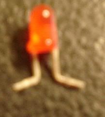
Cut yourself 2 small lengths of wire and strip them at both ends. Also get your LED out and bend the wires out to the side where there is a little notch on the wires and cut them. It will make a shape like this.
Step 6
Solder 1 of the wires to the "5" hole. By this I mean take the part of the wire thats stripped and stick it down in the hole leaving a little sticking out. Then take some solder and solder directly on the wire. It will ball up just enough to also get solder on the rim of the "5" hole which will attach this wire to it (this is your ground). Next you need to take the other wire and solder it to the leg where the RED wire connects as seen in this picture
On the left side of that plug you can see 4 wires going to the board. You must solder directly to the bottom most wire. This is very delicate here so be careful.
Step 7
Once these 2 wires are soldered to the board reconnect the flimsy controller film to the PCB just through the ribbon connector (thats the wide one that plugs into the left side). Once youve done this you can take the rubber section from the front piece of the controller (the plastic piece you set aside) this is the rubber piece that has the start and select buttons on it. If you place it on the film and press down on it it should turn the controller on.
Step 8
Once you have the controller turned on you can remove this flimsy film piece again and it should stay on. You then need to take your LED and try to connect it (just by holding it in place) to the 2 wires you just soldered to the main board. This will allow to figure out which way the LED is supposed to connect (if you put it on backwards it wont light up) Once you've figured it out you should set it aside and tin the ends of the wires (this involves getting solder to build up on the wires and dry allowing you to easily solder the LED to it) Once the wire is tinned you can solder the LED to the 2 wires. If the controller is still on the LED should light up. If not check all your connections and try again
Step 9
Once this is done you should cut the clear rubber piece that sits behind the PS button (this is the clear rubber piece that fits inside the black plastic piece that the flimsy button film is attached to right in that black rubber piece that you started the controller with) You only need to cut off that tube piece that comes down on the clear rubber piece. This allows the LED to sit in that shaft directly under the PS button
Step 10
If the LED doesnt fit in the black plastic piece you must melt down or cut off the tube ( I melt mine down because you already have the soldering iron out)
Step 11
Once this is done you can reconnect the flimsy piece back to the PCB via the 2 connectors. Carefully place it back on top of the PCB (allowing the LED to fit in the hole in the middle) There is a piece that fits into the top-left of the PCB which connects the two pieces make sure it goes in that hole. Also make sure that your wires arent blocking the plastic piece from sitting snug on the board (There are some spacers that keep the plastic piece separated from the PCB, these will sometimes hit the wires so make sure they are out of the way) Also before you put the controller back together put the analog sticks back on the PCB and make sure they have full movement without hitting the wires.
Step 12
Put the controller back together. THere is a plastic piece that separates the L1 and L2 and R1 and R2 buttons, make sure everything is slid back into place correctly, this can be difficult. Also make sure all your rubber pieces are placed back into the front piece of the controller (this includes the clear rubber piece that goes in the black rubber piece that sits behind the PS button. Once all that is in screw the PCB back into the controller, then Screw the rear piece back on the controller. And you should be done
There it is. The 12 step program for installing an LED in the PS3 remote
Here is a helpful link for how to solder
http://www.aaroncake...nics/solder.htm
Post by: FmanFORPS3 on January 06, 2007, 06:36:00 PM
Post by: GeKKoXP on January 06, 2007, 08:12:00 PM
.
Post by: pablot on January 07, 2007, 12:24:00 AM
Now, that pad is definitely for a resistor, not a capacitor. It connects to the leg of a MCU, so having a capacitor there makes no sense. The reason why there is no signal from the MCU is pretty evident. They didn't include the LED on the board so why should they control it from firmware? There really is no reason for it. So that is just a dead point. I guess you can use the led pads to easily mount the resistor and then use the resistor pad to patch in a wire to ground. It'll make a neat and clean install.
/pablot
Post by: PDAIsAok on January 07, 2007, 02:41:00 PM
PDAisAok thanks a bunch for the help. Il try it soon, and if not, I'll most likely send it to you. Once again, that is very helpful, still confusing with all this melting and solder stuff, but your post is very helpful and educating. Thanks a lot! Oh yea, how much is all this going to cost (getting the parts like solder iron, solder, iron, led and other)
25w Soldering Iron - $10.00
5mm Blue LED (if thats what you want) - Anywhere from $0.75 to $5 (I paid $5 for one at RadioShack)
Solder - $2.50 (rosin core)
Wire - $2.00 (you could find it cheaper but thats for a spool I believe)
Snips or wire cutters - $2.50
Tiny screwdriver set - $3.00
A knife - $0 Assuming you have one already
Total (with $5 overpriced LED from Radioshack) $25 + tax
Total (with cheap ass online LED) $20.75 + tax
Post by: ebphondaprelude on January 07, 2007, 04:23:00 PM
1st here are some hi-res shots of the front and rear, i would post them here but they are pretty big pix, so here are links
Front
http://myacc.net/~eu...s3/pcbfront.JPG
Back
http://myacc.net/~eu...ps3/pbcback.JPG
2nd, I changed up a few things on the controller.
A. Replaced 0603 led with a PLCC2 led
B. Changed power source for controller posistion leds, and added a resistor
Here is a shot with the controller turned off, as you can see the PLCC is a lot bigger then the 0603 and is flat, it still only runs 2.8v but is much brighter. I could not find a switchable 3.7v source, all the 3.7v sources I found were always on no matter if the controller was on or off. heres what it looks like.

Next I covered the power contacts for the 4 indicator leds at the top, I soldered down all 4 ground points, then the bigger trace that is right under the leds but just above the black connector is 3.7v. so i picked that for my power source. Now since the leds on the top are turned off by the ground points it is ok to always give them constant power (as the original ones had constant power as well), I used a 22ohm resistor to bring down the power to about 3.3v. then a wire from the top of the resistor across all the top (positive) of the leds
here is a pic up close

So how much brighter is it you ask, well i would say now they look right, lets see

And last but not least the final product

I would like to thank everyone who contributed to this thread i cant beleive it got so many views and got so big, and without all the help from the scene it wouldnt have been accomplished.
Stay tuned for more ;-)
Post by: PDAIsAok on January 07, 2007, 05:03:00 PM
hey, how come pdaisaok's picture has 4 coloured wires and the other picture shown on this thread doesnt?
The PCB board will stay on with nothing connected to it besides the battery
Eb, Very Nice! Did you use a different power source in order to get brighter LEDs for the SMDs?
Post by: ebphondaprelude on January 07, 2007, 05:43:00 PM
Post by: theBloodShed on January 07, 2007, 06:38:00 PM
Someone asked why I believe the empty pad is a resistor. I'll avoid numerics and speak generally... Makes things far easier for me. Having a resistor there allows you to limit the current and the voltage that an LED is subjected to, allowing it to turn on without blowing up. A capacitor, on the other hand, wouldn't have the same effect. If a capacitor was placed in that position, it would block the power attempting to flow through the LED. It would build up a charge instead of allowing electrons through, essentially cutting the LED off from a power source.
I know what a resistor and capacitor are. Seriously, I'm not completely ignorant; I'm just no expert. I've taken a couple classes and I've built small electonic projects from analog sound amplifiers to digital video encoders. Anyway, since my image ended up being backward anyway, it's just a pass through for a positive feed to the IC. It could be a resistor if the IC needs less than 2.8V but it could be a capacitor if the IC needs a more consistant power. The positive side is always live.
QUOTE(pablot)
theBloodShed: That led is definitely the wrong way around in your picture. I would suggest that you change it before someone breaks something.
Yeah, I had already realized that after I actually tested the board. Unfortunately, I made a new image but it looks like the forum doesn't allow post edits after a certain time.
QUOTE(pablot)
Now, that pad is definitely for a resistor, not a capacitor. It connects to the leg of a MCU, so having a capacitor there makes no sense. The reason why there is no signal from the MCU is pretty evident. They didn't include the LED on the board so why should they control it from firmware? There really is no reason for it. So that is just a dead point. I guess you can use the led pads to easily mount the resistor and then use the resistor pad to patch in a wire to ground. It'll make a neat and clean install.
You could be right, but without a datasheet for that IC there is no "definitely". Hell, it could even be for a 0 ohm resistor making it nothing more than a bridge. Anyway, it's true that the firmware on the chip may ignore that point completely. It's too bad.
I did find this interesting document. On page 8 they show the controller's mainboard and they took the metal casing off that chip. The chip is labeled SCEI (Sony Computer Entertainment International I assume) and CSR. It also looks like it has some flash memory and a built-in crystal oscillator.
Post by: pablot on January 08, 2007, 04:04:00 AM
Yeah, I had already realized that after I actually tested the board. Unfortunately, I made a new image but it looks like the forum doesn't allow post edits after a certain time.
You could be right, but without a datasheet for that IC there is no "definitely". Hell, it could even be for a 0 ohm resistor making it nothing more than a bridge. Anyway, it's true that the firmware on the chip may ignore that point completely. It's too bad.
PM me the address to the new picture and I'll replace it for you (I can do that).
And well.. I work with electronics and that pin on the mcu is used to ground the LEDs. There is no reason for that component to be capacitor. It is definitely a resistor. It can be a 0ohms resistor if the voltage is right, but it is a resistor.
/pablot
Post by: pablot on January 08, 2007, 10:53:00 AM
/pablot
Post by: ebphondaprelude on January 08, 2007, 01:07:00 PM
Post by: Pugsly0014 on January 08, 2007, 02:07:00 PM
Adding a SMC 0603 LED to the spot labled LED5
adding a SMC resistor to the spot labled R35
I see where someone has added a LED to the spot labled LED5 but this pad is dead without also adding a resistor to the spot at R35.
Now... if the programmers did not remove the firmware implementing lighting up LED5 when charging, and when the battery is about to die thoes two parts would be the only thing needed.
I don't see any posts seeing where someone has added BOTH the LED (LED5) and the Resistor (R35) back onto the board.
This post has been edited by Pugsly0014: Jan 8 2007, 10:10 PM
Post by: pablot on January 08, 2007, 02:25:00 PM
QUOTE(theBloodShed @ Jan 7 2007, 01:20 AM)
Well, the left side is the positive 2.8V feed, so my picture is definitely backwards. However, that point coming from the chip is dead regardless if the controller is on or off. It doesn't apply ground or a positive voltage. Something else is definitely missing.
QUOTE(Pugsly0014 @ Jan 8 2007, 09:38 PM)
Um.. I went back and read it again. No one, and unless they took the post down has tried the following.
Adding a SMC 0603 LED to the spot labled LED5
adding a SMC resistor to the spot labled R35
I see where someone has added a LED to the spot labled LED5 but this pad is dead without also adding a resistor to the spot at R35.
that post pretty much covers it. The output from the MCU is hi-z, so it's like not connecting it to anything.
on the other hand... He could have just been measuring at a bad time. It might be on when charging or so, so yes. I guess that it could be useful if some one tries it. Didn't think of that scenario..
Post by: 9ks2k on January 08, 2007, 05:46:00 PM
Post by: ebphondaprelude on January 08, 2007, 05:37:00 PM
QUOTE(9ks2k @ Jan 8 2007, 07:17 PM)
NB with your new setup the top 4 leds stay on con stantly? so u cant tell that controller is assignment? also unique leds dont ship to NJ?? i dont get it?
the top 4 leds turn off and you can tell the assignment :-)
Post by: theBloodShed on January 08, 2007, 06:46:00 PM
QUOTE(pablot)
uhm, we are not bitching. We are simply discussing the matter.
Exactly. I asked because I was curious to know what the reasoning behind one or the other would be. Surely it would be better to just solder random parts on a $50 controller instead of learning.
QUOTE(Pugsly0014 @ Jan 8 2007, 09:38 PM)
I don't see any posts seeing where someone has added BOTH the LED (LED5) and the Resistor (R35) back onto the board.
As pablot pointed out, I already tested the point. I tested the line by checking the voltage with a multimeter from the positive side of LED5 to the left side of the missing point (it's not "R35" though). It's a closed circuit regardless of controller activity. I tried a few things thinking perhaps "it only turns on when PS is pressed" or "it only turns on when battery is low" or "it only turns on when starting the PS3", etc... It's a completely dead line. Furthermore, the positive line is always on so I wouldn't recommend using it unless you like to constantly charge your battery.
This post has been edited by theBloodShed: Jan 9 2007, 02:48 AM
Post by: 9ks2k on January 08, 2007, 08:07:00 PM
QUOTE(ebphondaprelude @ Jan 8 2007, 07:44 PM)
the top 4 leds turn off and you can tell the assignment :-)
well thats great now i just need somone to tell me where to get the leds cause unique leds wont send to any adress in nj eb u have any extras u could sell me? also what mods u have done to your lude?
Post by: ProChief CXVII on January 08, 2007, 08:16:00 PM
if i ever geta ps2 ill do this for sure!
Post by: PDAIsAok on January 08, 2007, 08:33:00 PM
QUOTE(9ks2k @ Jan 8 2007, 08:38 PM)
well thats great now i just need somone to tell me where to get the leds cause unique leds wont send to any adress in nj eb u have any extras u could sell me? also what mods u have done to your lude?
http://www.superbrig...ds.com/leds.htm
Or RadioShack
Post by: entermymatrix on January 09, 2007, 06:41:00 AM
Post by: PDAIsAok on January 09, 2007, 06:25:00 PM
QUOTE(entermymatrix @ Jan 9 2007, 07:12 AM)
Has anyone tested the battery drain while using a 5mm LED? Should a 5mm LED cause a good bit of battery loss? Thanks
I have a 5mm in 2 of my controllers and I havent noticed much of a battery life change at all
Post by: Laeq on January 10, 2007, 01:14:00 AM
In all reality, this has been somewhat of a new experience for me, since I have next to zero experience with soldering of any kind, besides what I've seen other people do. Anyway, I got these placed on my second controller, and being a beginner at this stuff, it was fairly difficult until like the last 2 leds. They're a bit dim, as was explained before. In my next attempt, when I get another controller, I'll try a different color, and the most recent method to make them brighter. Heck, I may try to fix this one later too.
here's the final product (for now):

Post by: gr8hifi on January 10, 2007, 01:26:00 PM
Post by: TALONTSx on January 13, 2007, 04:18:00 PM
Post by: TALONTSx on January 14, 2007, 12:42:00 PM
Post by: R-Dot-Yung on January 15, 2007, 12:44:00 PM
I wanna make one controller Red and the other one Blue,
So for the red controller, i need to buy a 5mm 3.7v Red LED right
for the blue controller i need a 5mm 3.7v Blue LED light, and four 3mm 2.8v Blue LED lights
is this correct, cuz i cant find any of these type of LED lights, HELLLLP
Post by: bigjimmy on January 15, 2007, 02:07:00 PM
Post by: G0t M4xx 21 on January 18, 2007, 10:09:00 PM

Post by: ebphondaprelude on January 19, 2007, 10:17:00 PM
did you do the full voltage mod
Post by: Elusid on January 22, 2007, 01:47:00 AM
Post by: Frozenflame5050 on January 28, 2007, 01:50:00 AM
Post by: gr8hifi on January 28, 2007, 07:30:00 PM
Post by: topdoggb on March 08, 2007, 08:54:00 PM
Just shove each end of a small enough wire through the holes and solder it from the back, then cut off the excess. This will also make it much sturdier since everything will be soldered down.

Post by: dioioib on March 10, 2007, 11:30:00 PM
QUOTE(topdoggb @ Mar 9 2007, 12:01 AM)
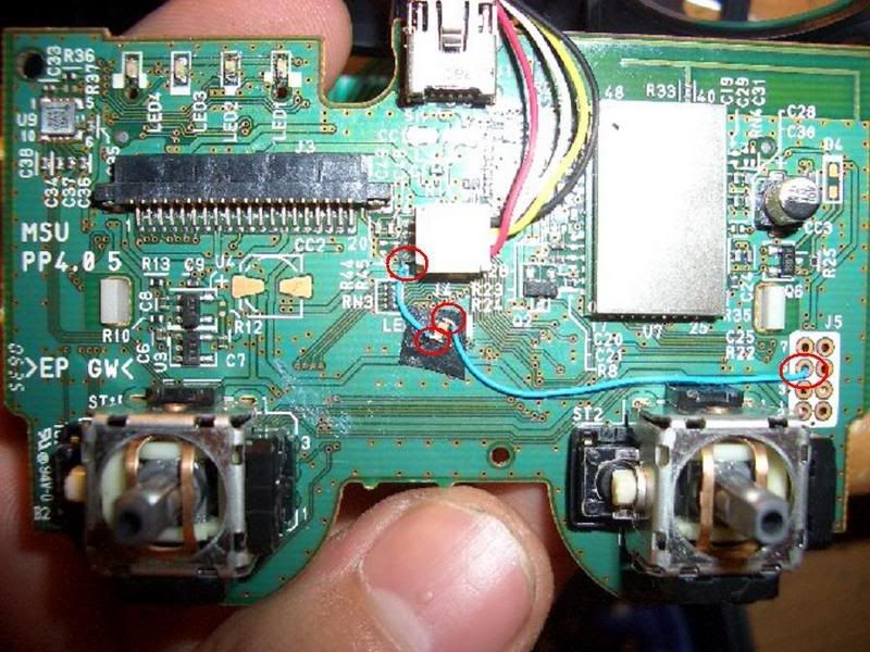
If you are using a surface mount led for the PS button (the size used for the controller number indicators) then you can make things simpler by soldering the led where it was intended to go (LED5) and then connecting the end of the blue trace to any of the holes circled in red on the circuit board with a very short wire. This is possible because of the fact that the missing resistor breaks the circuit, so you can complete it by grounding the end. FYI, every one of the small holes that don't connect traces on the board are ground. They are there to connect the top layer ground plane to the bottom layer ground plane.
Just shove each end of a small enough wire through the holes and solder it from the back, then cut off the excess. This will also make it much sturdier since everything will be soldered down.
Just hoping someone might have a solution I am having problems with LED 3. The bottom contact does not seem to be making a connection. So LED 3 has no power everything else works fine though. Is there any way I can bypass this contact and use another solder point on the board to get it working?
Post by: topdoggb on March 11, 2007, 09:05:00 AM

Post by: topdoggb on March 11, 2007, 10:14:00 AM
Post by: MattZani on April 03, 2007, 07:18:00 AM
QUOTE(G0t M4xx 21 @ Jan 19 2007, 06:16 AM)
I just did this mod to two PS3 controllers for Mattyv, i think they turned out pretty good:
Hi, what LED's do i need to get the same glow in the above's PS Button? it looks just right to me!
i'd like to add a red PS button to one, and go completely Blue with the other, what parts would i need so i could just unsolde the existing controller# LED's and replace? If possible i want it to look as clean as possible, and i know that i have to add wires to the PS Button LED, but can i use the same LED as the controller # LED's? to give a dim glow. im reasonably skilled with a soldering iron, but don't have £35 to throw away, so i want to get this right first time!
i know how to do the PS button, but can someone post a quick Tut on how to do the controller # LED's? with some quick pics?
Thanks!
Matt
PS3Center.net Member, Home of the White,Silver and Red PS3's!
Post by: argen_213 on April 25, 2007, 06:01:00 PM
QUOTE(FmanFORPS3 @ Jan 4 2007, 10:22 PM)
Just to double check, all you have to do is solder two wires, and an LED (the blue wires in the picture...) correct? and did you solder the (left) blue wire to the port across the red wire (the center of the controller)
Also, how do I go about changing the four red LEDs (that tell you the controller port). So I just break them off and solder blue ones (that are also 2.8v)?
And my last question, does the center LED turn off when the controller is off? or does it continuously drain the battery? (I've heard from a different modder that his first attempt drained the battery even when its off...)
BTW great work guys...you make it seem so...easy!
what is the exact type of led is this
Post by: argen_213 on April 25, 2007, 06:35:00 PM
QUOTE(FmanFORPS3 @ Jan 5 2007, 01:45 PM)
to anyone who is still confused (as was I), you pretty much have to just follow the picture. Solder one blue wire from the '5' hole to the LED, and one wire from the LED to the center of the board (the leg where the red LED plugs in). Thats it!
(yeah, I used paint
)BTW, I know I'm repeating all of this, but I'm sure some people will still be confused..
what kind of led is this
Post by: grim_d on April 29, 2007, 09:01:00 AM
QUOTE(argen_213 @ Apr 26 2007, 02:11 AM)
what kind of led is this
smd 0603
Post by: l0tics on May 01, 2007, 06:51:00 AM
These will work right?
Post by: topdoggb on May 01, 2007, 07:40:00 PM
Post by: wizz87 on May 03, 2007, 02:30:00 PM
Post by: l0tics on May 04, 2007, 09:46:00 PM


First controller went fine,
but the second one I tried was horrible. I ripped most of the solder pads off while removing the old leds... now it has no lights
Post by: l0tics on May 05, 2007, 11:16:00 AM
(IMG:http://glitches.planettonyhawk.gamespy.com/ftw/360led3.jpg)
(IMG:http://glitches.planettonyhawk.gamespy.com/ftw/360led4.jpg)
Post by: l0tics on May 05, 2007, 10:09:00 PM
(IMG:http://glitches.planettonyhawk.gamespy.com/ftw/360rol1.jpg)
(IMG:http://glitches.planettonyhawk.gamespy.com/ftw/360rol2.jpg)
Post by: l0tics on May 06, 2007, 12:36:00 AM
Post by: assesoffire on June 23, 2007, 05:28:00 PM
I did the Sixaxis PS button mod with a white, 3mm LED
(IMG:http://i58.photobucket.com/albums/g246/assesoffire/CIMG1568.jpg)
(IMG:http://i58.photobucket.com/albums/g246/assesoffire/CIMG1567.jpg)
Sorry the pictures aren't very good
Post by: _X_Brently4_X_ on August 08, 2008, 03:51:00 PM
(IMG:http://i254.photobucket.com/albums/hh112/brently4444/0808081138.jpg)
(IMG:http://i254.photobucket.com/albums/hh112/brently4444/0808081511a.jpg)
Post by: JORDAN_FCB on August 16, 2008, 10:29:00 PM
Post by: Ktmrida4lyfe on September 19, 2008, 10:01:00 AM
Post by: tricey777 on March 08, 2009, 06:27:00 PM
Post by: maXXimus06 on March 10, 2009, 03:14:00 PM
i don't have the led5 on my board, i got my system christmas 07...( 80g )
i did mod my PS button pretty easy i thought...worst part was gettin the F@$*IN
thing back together....i also used a 5mm clear laser LED, as soon as i find the wifes camra
ill post sum pic's
anyone know how to put lights in the PS3 case?? iv asked around but get NO response.
Post by: tricey777 on March 14, 2009, 03:06:00 PM
look at the bottom right of the board just get 2 wires comming off the two contacts there and your sorted
Post by: maXXimus06 on March 15, 2009, 02:22:00 PM
Post by: maXXimus06 on March 17, 2009, 10:10:00 AM
and the other under the buttons. so im look for other spots to solder to....
Post by: frozenballs on March 25, 2009, 07:28:00 AM
Post by: frozenballs on April 04, 2009, 04:17:00 AM
QUOTE(frozenballs @ Mar 25 2009, 03:04 PM)
has anyone done this mod to a new style pcd dual shock 3 board please? i want to do it but have no where to connect my led to as it looks nothing like your pcb's
thanks for that fella but thats where im running my rapid fire mod from lol and to the guy who asked erlier in the thread the left contact is ground the right is power
Post by: tryintomod on April 15, 2009, 08:25:00 PM
QUOTE(l0tics @ May 1 2007, 02:27 PM)
These will work right?
Yes those will work. These will work too! 0603 SMD
Post by: Ben. on July 09, 2009, 07:31:00 AM
Is it needed?