xboxscene.org forums

Pages: 1 2 3 [4] 5 6 ... 8

Author Topic: Sixaxis Led Swap  (Read 1212 times)

entermymatrix

  • Archived User
  • Newbie
  • *
  • Posts: 8
Sixaxis Led Swap
« Reply #45 on: January 06, 2007, 08:11:00 AM »

The stuff provided in this thread is pretty step-by-step.

1)Take controller apaprt
2)Solder wire to LED
3)Solder wire to tilt-control power plug
4)Solder wire to #5 hole
6)Modify the black plastic piece and fit the LED inside (the black plastic piece is the plastic that the contoller buttons sit on)
7)Cut the white rubber cylinder that sits right under the PS button so that the LED will fit
8)Put the controller back together

That is pretty much step-by-step the way i did it. It's very simple once you get started. Like i said before, tearing the controller apart and rebuilding is the biggest time consumer.
Logged

numba107

  • Archived User
  • Newbie
  • *
  • Posts: 3
Sixaxis Led Swap
« Reply #46 on: January 06, 2007, 08:42:00 AM »

well now im startin to think this was a bad idea, my controller dies much faster n the light has been actin wierd mad.gif  mad.gif  mad.gif  mad.gif
Logged

ebphondaprelude

  • Archived User
  • Sr. Member
  • *
  • Posts: 251
Sixaxis Led Swap
« Reply #47 on: January 06, 2007, 09:19:00 AM »

what size led are you using that it dies that much faster,

i use an 0603 and notice no diffrence at all

Thx

<MikE>

Logged

aaquib2

  • Archived User
  • Newbie
  • *
  • Posts: 5
Sixaxis Led Swap
« Reply #48 on: January 06, 2007, 10:25:00 AM »

i really wanna do this! You think if I go to home depot they'd do it for me?

or picture instructions please!
Logged

theBloodShed

  • Archived User
  • Newbie
  • *
  • Posts: 30
Sixaxis Led Swap
« Reply #49 on: January 06, 2007, 10:40:00 AM »

QUOTE(NeoSHODAN @ Jan 5 2007, 05:54 AM) *

So I took my controller apart to find the missing resistor's pads.  I think I've managed pretty well, but it would be better if someone with a multimeter (one with exceedingly small probes) would go over my highlighting to ensure that I've followed the traces correctly.

Damnit, someone beat me to it.  I took pictures this morning and followed the traces.  Anyway, I think it's a capacitor that's missing and not a resistor.  I can't say for sure because the spot is not labeled, but almost everything else in the area is a capacitor.

I'm attaching my picture only because I wasted the time to make it.  =P

Unfortunately, I don't have any surface mount LEDs and capacitors to try it yet.

(IMG:http://memberuploads.xbox-scene.com/uploads/2007_01_09/02_54_28_PS3_Controller_wide.jpg)

This post has been edited by pablot: Jan 9 2007, 10:17 AM
Logged

NeoSHODAN

  • Archived User
  • Newbie
  • *
  • Posts: 2
Sixaxis Led Swap
« Reply #50 on: January 06, 2007, 11:06:00 AM »

I'm not sure if it's a capacitor or not...  Everything I've learned about electronics says that's a resistor...  and it looks like a resistor pad to me as well.  I could be totally wrong, but I still believe that's a resistor pad...  now if only someone would test it...
Logged

theBloodShed

  • Archived User
  • Newbie
  • *
  • Posts: 30
Sixaxis Led Swap
« Reply #51 on: January 06, 2007, 12:24:00 PM »

QUOTE(NeoSHODAN @ Jan 6 2007, 07:13 PM) View Post

I'm not sure if it's a capacitor or not...  Everything I've learned about electronics says that's a resistor...  and it looks like a resistor pad to me as well.  I could be totally wrong, but I still believe that's a resistor pad...  now if only someone would test it...

Well, all of the brown surface mount components are definitely capacitors (labeled starting with a "C").  While resistors are black (and labeled started with "R").  All I can say is that most of the other surface mount parts are capacitors but that's hardly reason that it should be one; I'm just guessing.  What leads you to believe it's a resistor?  I'm not electronic expert, I've just learned what I could so I'd like to know.  Maybe I'm missing something.

One thing is confusing me though... the "band" on the LED outline should be the negative side.  I labeled mine "backwards" because when I followed the other side of the trace (labeled "ground" on my pic), there is only a single capacitor (labeled "C18" on the back of the board) seperating it from ground.  While the other end goes straight to the blank spot that would connect it to the IC (which I'm pretty sure is the bluetooth module).
Logged

entermymatrix

  • Archived User
  • Newbie
  • *
  • Posts: 8
Sixaxis Led Swap
« Reply #52 on: January 06, 2007, 01:59:00 PM »

i used a 5mm led...has anyone else noticed their controller dying faster? I'm away from my PS3 so i haven't been able to test the battery life.
Logged

Pugsly0014

  • Archived User
  • Newbie
  • *
  • Posts: 2
Sixaxis Led Swap
« Reply #53 on: January 06, 2007, 02:27:00 PM »

Take a closer look and follow white line for R35.  This is a resistor for sure.  The fact that it is missing would indicate that this and the SMC LED in the LED5 position would be infact all that is missing to make this controller work like the ones they had in dev.  I already ordered 25 of each color from this site:  It only cost me $25.  I already have some surface mount resistors to put into the spot for R35.  

http://www.unique-leds.com/index.php

I am going to mod both of my controllers...

LED #1 Red
LED #2 Yellow
LED #3 Green
LED #4 Blue
LED #5 White

If this works... LED5 will come on when charging and when the battery is almost dead.  From what I heard this is how the DEV controllers worked.  I just hope they did not remove the firmware of the controller to keep this from happening.
Logged

theBloodShed

  • Archived User
  • Newbie
  • *
  • Posts: 30
Sixaxis Led Swap
« Reply #54 on: January 06, 2007, 02:55:00 PM »

QUOTE(Pugsly0014 @ Jan 6 2007, 10:34 PM) View Post

Take a closer look and follow white line for R35.  This is a resistor for sure.  The fact that it is missing would indicate that this and the SMC LED in the LED5 position would be infact all that is missing to make this controller work like the ones they had in dev.  I already ordered 25 of each color from this site:  It only cost me $25.  I already have some surface mount resistors to put into the spot for R35.

I did notice that line but there is a huge break in the printed line.  Traces do not run over top of the label printing.  Typical board labeling will work around any spots that are not printable.  I think R35 is the resistor to the left of the "C24" label because it is definitely a black resistor where the line stops.

Also notice that the line above the break also has a notch pointed at a capacitor to the left of C24.  I'm pretty sure this line is pointing to both the empty spot and the unlabeled capacitor next to C24.  I can only assume the labels are under the IC which is mounted on a raised "mini board".

I'm going to desolder a surface mount LED from an unused motherboard and get some resistors and capacitors from an unused HDD.  I'll try this out and see how it goes.  I'm going to wait to solder the LED until I run some tests with a multimeter.
Logged

FmanFORPS3

  • Archived User
  • Newbie
  • *
  • Posts: 6
Sixaxis Led Swap
« Reply #55 on: January 06, 2007, 04:28:00 PM »

Do you guys think a 3mm 2.2v LED will work? or is 2.8 volts too much for it to handle?
Logged

PDAIsAok

  • Archived User
  • Newbie
  • *
  • Posts: 14
Sixaxis Led Swap
« Reply #56 on: January 06, 2007, 04:45:00 PM »

QUOTE(FmanFORPS3 @ Jan 6 2007, 05:35 PM) *

Do you guys think a 3mm 2.2v LED will work? or is 2.8 volts too much for it to handle?


Im pretty sure that means 2.2v max so I would recommend using something with a higher voltage.
Logged

aaquib2

  • Archived User
  • Newbie
  • *
  • Posts: 5
Sixaxis Led Swap
« Reply #57 on: January 06, 2007, 05:13:00 PM »

QUOTE(PDAIsAok @ Jan 6 2007, 01:41 PM) View Post

Im listing one on eBay if anyone wants it!

http://cgi.ebay.com/...em=110076335457


id pay $15 if you sent me all the equipment needed + picture instructions. Ive never soldered or grounded anything before, and I want to do this with MY controller.
Logged

theBloodShed

  • Archived User
  • Newbie
  • *
  • Posts: 30
Sixaxis Led Swap
« Reply #58 on: January 06, 2007, 05:13:00 PM »

Well, the left side is the positive 2.8V feed, so my picture is definitely backwards.  However, that point coming from the chip is dead regardless if the controller is on or off.  It doesn't apply ground or a positive voltage.  Something else is definitely missing.

Unfortunately, I couldn't find anything on the Alps Electric website for details on the chip to discover what that pin might be.  So basically it's a dead end attempting to complete the circuit and probably requires more component(s) on another IC pin.

The main thing I don't like is that just connecting ground will cause the LED to be lit all of the time.
Logged

PDAIsAok

  • Archived User
  • Newbie
  • *
  • Posts: 14
Sixaxis Led Swap
« Reply #59 on: January 06, 2007, 06:20:00 PM »

QUOTE(aaquib2 @ Jan 6 2007, 06:20 PM) View Post

id pay $15 if you sent me all the equipment needed + picture instructions. Ive never soldered or grounded anything before, and I want to do this with MY controller.


If you've never soldered before this really isnt the place to start as this is a very small area you are working with and requires some very delicate solders.  That being said, Here are detailed instructions, as detailed as I know how to be, for you to do this on your own.  If you want you can send me your controller and Id install everything for $15, you must pay for shipping both ways though which wouldnt be too expensive.  Just let me know if thats something you would rather do.  This isnt really all that difficult but it can be time consuming


SUPPLIES NEEDED

1 x PS3 controller
1 x Wire (got mine at RadioShack its a little thick but it works, get the thinnest stuff they have)
1 x soldering Iron (lower wattage is better so you dont do damage to your board, 15w is good but will take awhile for solder to melt, I used a 25w without problems)
1 x LED  (You can use the SMD LED if you can get one but RadioShack won't have these, so your best bet will be a 3mm LED.  You can use a 5mm but its an extremely tight squeeze but its much brighter.  I got a 3.7v 5mm LED and it worked fine, just make sure it can do AT LEAST 2.8v)
1 x Solder (doesnt take much so get a small thing of it)
1 x Tiny screwdriver for the case screws and 1 screw holding PCB to controller
1 x cup (to hold all the pieces to the controller while you're working)


Step 1

Take the controller apart.  There are 5 screws holding the case together, put screws in cup.  Take the back of the controller off, its snapped into place so it will take a little work, be careful though

Step 2

Once the back is off there is 1 silver screw holding the PCB to the controller that you need to remove.  It is behind the battery pack, put screw in cup

Step 3

remove PCB from controller, once removed set aside the front part of the controller

Step 4

There is a thin ribbon connector and small 4 pin plug holding the flimsy film for the buttons to the PCB, remove this from the PCB and set aside.  It has the L2 and R2 attached to it, leave it that way

Step 5

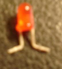
Cut yourself 2 small lengths of wire and strip them at both ends.  Also get your LED out and bend the wires out to the side where there is a little notch on the wires and cut them.  It will make a shape like this.

IPB Image

Step 6

Solder 1 of the wires to the "5" hole.  By this I mean take the part of the wire thats stripped and stick it down in the hole leaving a little sticking out.  Then take some solder and solder directly on the wire.  It will ball up just enough to also get solder on the rim of the "5" hole which will attach this wire to it (this is your ground).  Next you need to take the other wire and solder it to the leg where the RED wire connects as seen in this picture

IPB Image

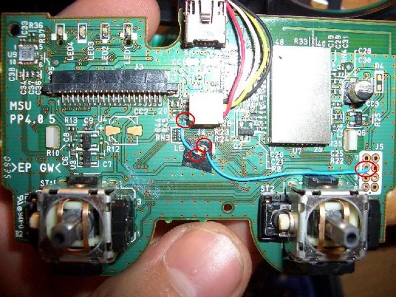
On the left side of that plug you can see 4 wires going to the board. You must solder directly to the bottom most wire.  This is very delicate here so be careful.

Step 7

Once these 2 wires are soldered to the board reconnect the flimsy controller film to the PCB just through the ribbon connector (thats the wide one that plugs into the left side).  Once youve done this you can take the rubber section from the front piece of the controller (the plastic piece you set aside)  this is the rubber piece that has the start and select buttons on it.  If you place it on the film and press down on it it should turn the controller on.

Step 8

Once you have the controller turned on you can remove this flimsy film piece again and it should stay on.  You then need to take your LED and try to connect it (just by holding it in place) to the 2 wires you just soldered to the main board.  This will allow to figure out which way the LED is supposed to connect (if you put it on backwards it wont light up)  Once you've figured it out you should set it aside and tin the ends of the wires (this involves getting solder to build up on the wires and dry allowing you to easily solder the LED to it)  Once the wire is tinned you can solder the LED to the 2 wires.  If the controller is still on the LED should light up.  If not check all your connections and try again

Step 9

Once this is done you should cut the clear rubber piece that sits behind the PS button  (this is the clear rubber piece that fits inside the black plastic piece that the flimsy button film is attached to right in that black rubber piece that you started the controller with)  You only need to cut off that tube piece that comes down on the clear rubber piece.  This allows the LED to sit in that shaft directly under the PS button
 

Step 10

If the LED doesnt fit in the black plastic piece you must melt down or cut off the tube ( I melt mine down because you already have the soldering iron out)

Step 11

Once this is done you can reconnect the flimsy piece back to the PCB via the 2 connectors.  Carefully place it back on top of the PCB (allowing the LED to fit in the hole in the middle)  There is a piece that fits into the top-left of the PCB which connects the two pieces make sure it goes in that hole.  Also make sure that your wires arent blocking the plastic piece from sitting snug on the board (There are some spacers that keep the plastic piece separated from the PCB, these will sometimes hit the wires so make sure they are out of the way)  Also before you put the controller back together put the analog sticks back on the PCB and make sure they have full movement without hitting the wires.

Step 12

Put the controller back together.  THere is a plastic piece that separates the L1 and L2 and R1 and R2 buttons, make sure everything is slid back into place correctly, this can be difficult. Also make sure all your rubber pieces are placed back into the front piece of the controller (this includes the clear rubber piece that goes in the black rubber piece that sits behind the PS button.  Once all that is in screw the PCB back into the controller, then Screw the rear piece back on the controller. And you should be done


There it is.  The 12 step program for installing an LED in the PS3 remote


Here is a helpful link for how to solder

http://www.aaroncake...nics/solder.htm
Logged
Pages: 1 2 3 [4] 5 6 ... 8